You have heard it said that a picture is worth a thousand words. This is undoubtedly the case when it comes to welding symbols.
Welding is a process that combines two materials using heat or pressure. Welding symbols indicate the type of weld, the size and shape of the weld, and other details.
There are dozens of different welding symbols, which can confuse someone just learning about welding. In this blog post, we will take a look at some of the most common welding symbols and what they mean.
This will help you understand the welding basics to start your next project confidently.
Welding symbols are a quick way of providing welders with important information. Just like the “check engine” or “oil change” lights on your car, these symbols use images to communicate necessary messages. Paying attention to these symbols is essential to maintaining equipment and avoiding injury.
Of course, symbols are only helpful if you know what they mean. Without this understanding, even the most valuable characters will look like Greek to you.
Here are some of the most common welding symbols you need to know about and short explanations of what they need. With this information in hand, you will be ready to get started on your next welding job.
Review contents
Why Learn Welding Symbols?
To someone unfamiliar, welding symbols might look like some strange hieroglyphics. Why go through the trouble of learning how to read them?
Welding is a profitable career that requires relatively little training. According to the Bureau of Labor Statistics, average welders make almost $40,000 yearly and don’t need a degree for an entry-level position. Many specialized jobs, however, can have a much higher salary.
But even though welding doesn’t require a college education, it requires specialized training. Learning to read these symbols is one of the first steps in pursuing that training. This knowledge could provide you entry into a stable career path.
Understanding Symbol Basics
Before we look at specific weld symbols, let’s look at a basic overview of what these symbols are and how they work.
Consistency of Symbols
For the most part, symbols are consistent across the welding profession. There are some specifics. However, that may be specific to a particular shop or tool.
Even so, learning the essential elements of a welding symbol is worthwhile since most shops comply with the American Welder’s Society Society standards. Whenever you start at a new shop, check what standards they follow with their symbols. This will help you accurately read the welding drawing you have.
How Symbols Work
The purpose of a weld symbol is to give instructions about how the weld should be done. These symbols indicate the type of weld, its size, and its location.
Also, sometimes welding characters show where the welder should work and what tools the welder should use.
The Arrow
The first part of the symbol to identify is the arrow. The arrow is critical because it points to the joint that must be welded. It also identifies different sides of the joint.
In the drawing, the arrow will point at a joint. The side of the joint that the arrow is pointing at is called the “arrow side,” and the arrow it is not pointing at is called the “other side.” The drawing can instruct how to weld the arrow or the other side.
Sometimes, a drawing will have more than one arrow coming off the same symbol to save space. This is permissible if more than one joint is being welded similarly.
Read Next – Lincoln Electric VIKING 3350 Black Welding Helmet Review
The Reference Line
If the arrow indicates where the weld should be done, the reference line indicates how it should be done. The reference link is a horizontal line that connects to the arrow. The arrow can be connected to either side of the line.
The reference line can give the welder information about both the arrow side and the other side of the joint. Any information about the arrow side will appear below the reference line. Information about the other side will appear above it.
In some cases, there may be several tasks that the welder must perform in a specific order. To show this, the drawing may use multiple reference lines. The lines closest to the arrow are the tasks that should be performed first.
The Juncture
The space where the arrow and the reference line connect is called the juncture. Sometimes, additional symbols will be attached to the juncture, giving more information about how the weld should be done.
For instance, a flag growing out of the juncture indicates that the weld should be done in the field. The weld should be done back at the shop if there is no flag.
Another common symbol at the juncture is an open circle. This symbol indicates that the weld should go around the joint.
The Tail
The next part of the welding symbol to continue is the tail. The tail is a greater than (>) or less than (<) symbol. This tail is then connected to the end of the reference line opposite the arrow.
The purpose of the tail is to provide information that cannot be communicated anywhere else on the symbol. This information can appear on the left or right side of the table.
A standard reference on the tail is information about the approved welding procedure specification (WPS).
This formal document outlines how to perform a specific weld according to code requirements. Typically, the drawing represents the WPS by including specific designation letters along the tail.
Additional Information in Symbols
Most of the specific information you need about the weld can be found in the welding procedure specification. Even so, welding symbols will often include additional information.
Groove Welds
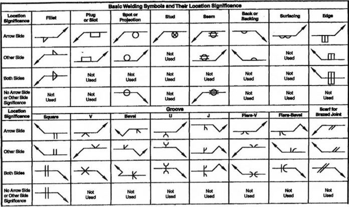
Different kinds of grooves, like J, V, and U grooves, can increase the size of a weld on a joint. The drawing might add the groove symbol to the welding symbol.
If the groove symbol is below the reference line, it only applies to the arrow side. It only applies to the other side if it is above the reference line. If it is on both sides, then it is a double weld. The groove weld symbol will usually include information about the groove’s depth and angle.
Complete Joint Penetration
There are several ways that a symbol might indicate the need for complete joint penetration (CJP). The first way is to add the letters “CJP” to the tail of the symbol. This symbol indicates that full mutual penetration is required but does not specify how to do it.
A more specific way to indicate complete joint penetration is to use the symbol for a groove weld. Then, the drawing would show the need for CJP by not recording the depth of the weld.
Fillet Weld
Fillet welds are standard in industries using boilers and pressure vessels. The primary symbol for a fillet weld is a right triangle.
Typically, this triangle appears on the reference line, and the perpendicular lead appears on the left. If the fillet weld occurs on both sides of the joint, the symbol will appear above and below the reference line.
Plug and Slot Welds
Plug and slot welds are used when welding two members together, one of which has holes. As one piece of metal is welded, the welded material fills the gaps in the other piece.
For a plug weld, the drawing will show the diameter of each plug at the left. On the right, you will see the spacing between each plug.
For a slot weld, the information on the left is the length of each slot. On the right, the drawing shows the depth and width of the slot.
For the total number of plugs or slots, there is a number in parentheses below the drawing. Also, if the plugs or slots are not filled with welded material, the appropriate depth will appear in the drawing.
Letters to Look For
We have already mentioned some letters that you may see appearing in welding symbols. There are a few more letter combinations you should be aware of.
For instance, if the weld includes air cutting, you will see the letters “AC.” Adding an A, C, or M indicates specific types of air cutting, like air-carbon, carbon arc, and metal-arc air cutting.
There are also common suffixes that may be added to specific types of cutting. AU indicates automatic cutting, while I indicate machine cutting. Also, manual cutting is shown by MA, while SA offers semi-automatic.
The Three Basic Welding Symbols
Welding symbols are used to communicate information about a welding joint. They are typically found on drawings and blueprints.
There are three basic types of welding symbols: the groove weld, the fillet weld, and the flare bevel weld.
The groove weld symbol is used to indicate a groove weld. A groove weld is made by joining two pieces of metal together in a V-shaped groove. The size, depth, and angle of the V-shape will be specified on the drawing.
The fillet weld symbol is used to indicate a fillet weld. A fillet weld is made by joining two pieces of metal together at an angle. The size of the pitch will be specified on the drawing.
The flare bevel weld symbol is used to indicate a flare bevel weld. A flare bevel weld is made by joining two pieces of metal together at an angle with a flared edge. The size and grade of the flare will be specified on the drawing.
Read Next – Best Welding Tools And Accessories For You in 2022
The Seven Most Common Welding Symbols
There are seven common welding symbols, and they are:
- The fillet weld symbol is two lines intersecting at an angle, usually 45 degrees.
- The groove weld symbol is a pair of parallel lines.
- The spot weld symbol is a dot inside a circle.
- The plug or slot weld symbol is a rectangle with rounded corners.
- The seam weld symbol is two parallel lines with a zigzag line between them.
- The surface weld symbol is a series of short lines perpendicular to the main welding line.
- The braze weld symbol is a series of small circles along the welding line.
What is the most common welding symbol?
The most common welding symbol is the fillet weld. A fillet weld is a circular weld that joins two pieces of metal together at right angles.
It is the most common type of weld because it is strong and can be used on both thin and thick metals.
What is the ten most common welding defect?
Welding is joining two materials, usually metals or thermoplastics, by using high heat to melt the materials and create a strong bond.
Welding is used in various industries, from construction to manufacturing, and many different welding methods and techniques exist.
Welding defects can occur for various reasons, including incorrect welding procedures, harmful materials, or operator error.
Defective welds can lead to big problems, so it’s essential to be aware of the most common welding defects and how to avoid them.
Porosity
Porosity is one of the most common welding defects caused by trapped gases within the weld metal. Porosity can weaken the weld and make it more susceptible to corrosion. To avoid porosity, ensure good gas coverage during welding and use clean consumables.
Incomplete Fusion
Incomplete fusion happens when the weld metal doesn’t completely fuse with the base material. This can occur if the welder moves too fast or has too much heat input. Incomplete fusion can cause cracking and weakness in the weld joint. To avoid incomplete fusion, use filler metals that match the base material composition and follow proper welding procedures.
Undercut
Undercut occurs when the edge of the weld bead melts away faster than the rest, leaving a minor groove on the edge of the weld joint.
Spatter
Spatter is tiny droplets of molten metal ejected from the welding arc. Spatter can cause porosity and crack, making the weld joint more challenging to inspect. To reduce spatter, use lower welding currents and voltages.
Slag Inclusion
SlSlag is a non-metal material that forms during welding to protect the weld pool from atmospheric contamination. Ag inclusion occurs when bits of slag from the welding process is trapped in the weld metal. Slag inclusion can weaken the weld and make it more susceptible to cracking. To avoid slag inclusion, use proper welding techniques and remove all slag from the weld joint before cooling.
Lack of Penetration
Lack of penetration can cause cracking and weakness in the weld joint. Lack of penetration happens when the weld bead doesn’t penetrate the base material. This can occur if the welder moves too fast or has too much heat input. To avoid a lack of penetration, use filler metals that match the base material composition and follow proper welding procedures.
Cracking
Cracking is one of the most severe welding defects as it can cause complete failure of the weld joint. Cracks can be caused by various factors, including welding too fast, incorrect filler metal, and poor joint design. To avoid cracking, use proper welding techniques and procedures, and inspect the weld joint for cracks after welding.
Warping
Warping can make it challenging to assemble parts or fit them into place. Warping can occur when the heat from welding causes the metal to expand and distort. e. To avoid distortion, use proper welding techniques and allow the metal to cool slowly after welding.
What are welding symbols used for?
Welding symbols indicate the type of weld, size, angle of the weld, and other important information. They are usually found on drawings or blueprints.
What are the five common welding joints?
There are five common welding joints: butt, corner, lap, tee, and edge.
Each joint has its own set of welding symbols that specify the joint, the size and thickness of the materials used, the weld bead geometry, and other information.
Read Next – Best Tig Welding Machine Aluminum Our Top Picks
What do 1F, 2F, 3F, and 4F mean in welding?
1F, 2F, 3F, and 4F refer to the degree of slope on a weld. 1F is a 30-degree bevel, 2F is a 45-degree bevel, 3F is a 60-degree bevel, and 4F is an 80-degree bevel.
The most common welding symbol is the fillet weld. A fillet weld joins two pieces of metal at right angles.
The size of the fillet weld is indicated by a number (1, 2, 3, or 4), which corresponds to the leg length of the triangle that would enclose the weld if it were drawn on paper. For example, a 1″ fillet weld would have legs that are 1″ long.
The bevel angle is indicated by a letter (F for flat, V for vertical, or O for overhead).
For example, a 1F weld indicates a 30-degree slope (the angle between the two pieces of metal being joined), while a 4V weld indicates an 80-degree angle.
What are the four main parts of the welding symbol?
Welding symbols are used on blueprints and drawings to show where the weld is to be placed, how it is to be made, and what type of weld is required. A welding symbol has four main parts: reference line, arrow, sign, and specifications.
The reference line is a straight line that shows the location of the weld. The arrow points to the side of the reference line, indicating the weld’s start. The symbol provides information about the type of weld that is needed.
The specifications give additional information about the weld’s size, angle, depth, and other details.
What are the five basic weld types?
There are five basic weld types: fillet, groove, spot, projection, and butt.
Fillet welds are the most common type of weld. They join two pieces of metal at an angle, usually 90 degrees. The weld is made by depositing a bead of welding material (usually metal) between the two pieces.
Groove welds join two pieces of metal that are flush with each other. The weld is made by depositing a bead of welding material into the groove between the two pieces of metal.
Spot welds are used to join two pieces of metal that are touching each other. The weld is made by depositing a small amount of welding material on the spot where the two pieces of metal touch.
Projection welds are used to join two pieces of metal that have a small gap between them. The weld is made by depositing a bead of welding material on the edge of one piece of metal and projecting it into the gap between the two pieces.
Butt welds join two pieces of metal that are flush with each other. The weld is made by depositing a bead of welding material along the edge where the two pieces of metal meet.
What does F mean by welding symbol?
The “F” in welding symbols represents the fillet weld. A fillet weld is a weld that joins two pieces of metal together at right angles.
It is typically used for structural applications, such as joining two beams.
There are three main types of fillet welds:
- Butt joint fillet weld: This is the most common weld used to join two pieces of metal at right angles.
- Corner joint fillet weld: This weld is used to join two pieces of metal at an angle other than 90 degrees.
- Tee joint fillet weld: This weld is used to join three pieces of metal together at right angles.
The size of a fillet weld is typically specified by its leg length, which is the length of the weld on each side of the joint. The most common leg lengths are 1/4″, 3/8″, and 1/2″.
Conclusion
Welding symbols are an essential part of every welder’s life, as they help to communicate the specific details of a weld.
This article has gone over the most common welding symbols and their meanings.
We hope this guide has helped you understand each symbol’s meaning and how to interpret them.
